The 25-Second Trick For Wedge Barriers
Table of ContentsSome Of Wedge BarriersThe Ultimate Guide To Wedge Barriers
The Basic Principles Of Wedge Barriers
The staying pressure used to
the cam web cam deploy release wedge plate 16 may might provided by an electromechanical actuator 84 or other various other. The spring setting up 54 and the actuator 84(e. Wedge Barriers. g., electromechanical actuator)may run with each other to convert the web cam and raise the wedge plate 16.
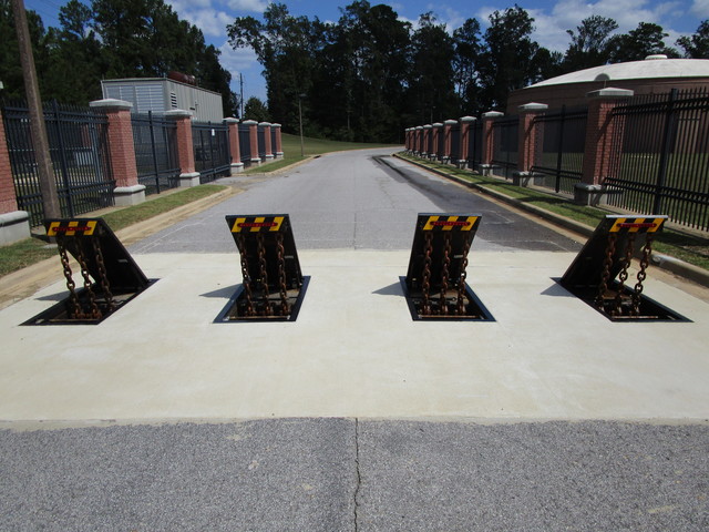
As discussed over, the spring setting up 54 puts in a constant force on the camera, while the electromechanical actuator may be controlled to exert a variable force on the camera, thus enabling the training and lowering( i. e., releasing and pulling back )of the wedge plate 16. In particular embodiments, the constant force applied by the spring setting up 54 may be adjustable. g., electromechanical actuator) is impaired. As will be appreciated, the spring assembly 54 may be covered and shielded from particles or other components by a cover plate(e. g., cover plate 68 shown in FIG. 4) that may be substantially flush with the raised surface 38 of the foundation 14. As pointed out over, in the deployed placement, the wedge plate 16 offers to obstruct access or travel past the barrier 10. The barrier 10(e. g., the wedge plate 16 )might obstruct pedestrians or automobiles from accessing a property or path. As talked about above, the barrier 10 is affixed to the anchor 30 secured within the structure 14,
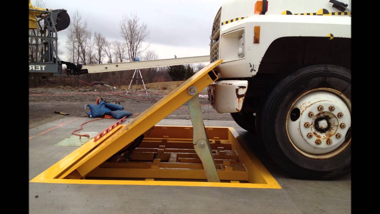
front braces 71. Therefore, the linkage settings up 72 might pivot and turn to make it possible for the collapse and expansion of the linkage assemblies 72 throughout retraction and release of the bather check this site out 10. The linkage assemblies 72 cause activity of the wedge plate 16 to be restricted. For instance, if a vehicle is traveling in the direction of the deployed wedge plate 16(e. For instance, in one circumstance, the safety and security legs 86 may be prolonged duringmaintenance of the barrier 10. When the safety and security legs 86 are deployed, the safety and security legs 86 support the weight of the wedge plate 16 against the surface area 12. Because of this, the lifting mechanism 50 might be shut down, serviced, gotten rid of, changed, etc. FIG. 5 is partial perspective view of a personification of the surface-mounted wedge-style barrier 10, showing the camera 80 and the cam surfaces 82 of the lifting device 50. Specifically, 2 webcam surfaces 82, which are referred to as reduced web cam surface areas 83, are positioned below the cam 80. The reduced camera surfaces 83 may be repaired to the surface 12 (e. For instance, the reduced webcam surfaces 83 and the mounting plate 85 may form a solitary item that is secured to the anchor 30 by bolts or various other mechanical bolts. Furthermore, two web cam surface areas 82, which are referred to as top camera surfaces 87, are placed over the see this webcam 80 and coupled to (e. In various other personifications, interfering layers or plates may be positioned read review between the surface area 12 and the reduced camera surfaces 83 and/or the wedge plate 16 and the upper webcam surface areas 87 As mentioned above, the cam
80 translates along the cam surfaces 82 when the wedge plate 16 is raised from the withdrawed placement to the released position. Additionally, as discussed above, the spring setting up 54 (see FIG. 3 )might supply a pressure acting upon the cam 80 in the direction 102 by means of spring rod 58, which may lower the force the electromechanical actuator 84 is required to apply to the camera 80 in order to actuate and raise the wedge plate 16. 1 )to the deployed setting(see FIG. 4). As revealed, the webcam 80 includes track wheels 104(e. g., rollers), which call and convert along the cam surface areas 82 throughout operation.